Computer science bachelor thesis · Goethe University Frankfurt · 2023
A bicycle that balances itself.
Original title: Entwurf einer Steuerung für ein selbstbalancierendes Fahrrad
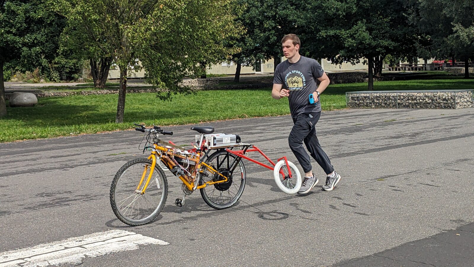
I wrote the control software for an existing full-size test bicycle. A BeagleBone Black ran the Linux application, while one of its real-time coprocessors measured the rear wheel. In the final documented test, the bicycle balanced after release for more than a minute while an operator ran nearby and used a remote to trim its direction.
Why this problem
The earlier work behind this platform compared two ways to counter a fall: add a reaction wheel, or steer the front wheel into the lean. This bicycle used the second approach. A motor above the head tube turned the handlebar, so the balance controller had to work through the same steering geometry used to change direction.
Other students had built and modified the mechanical and electrical platform before my thesis. My part was the software and control work described here: interfaces for the sensors and motor electronics, concurrent control loops, data logging, calibration, controller tuning, and the integrated test campaign.
One Linux board, one real-time coprocessor, two motors.
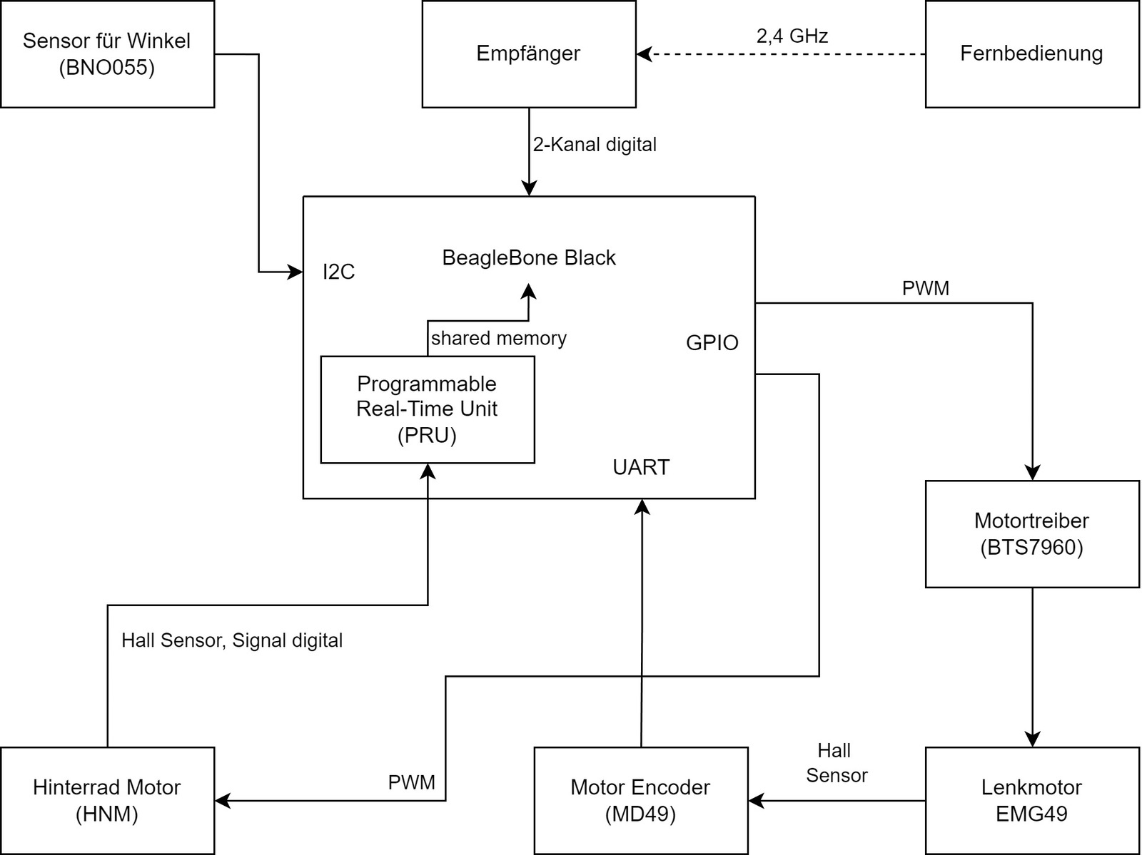
A BeagleBone Black sits at the center. A BNO055 orientation sensor reports lean over I²C, and an MD49 reads the steering motor encoder over UART. The remote receiver supplies speed and steering requests through an analog conversion circuit. PWM and GPIO outputs drive the BTS7960 steering electronics and the rear hub motor controller. One Programmable Real-Time Unit (PRU) counts the rear motor's Hall-sensor transitions independently of Linux scheduling.
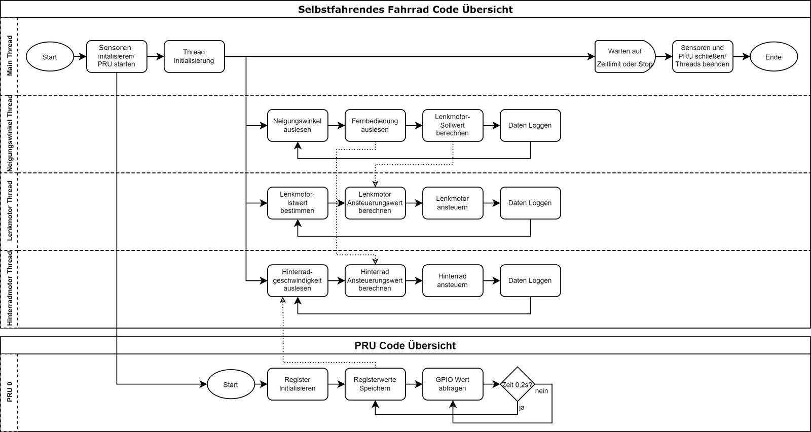
Four Linux threads and one PRU program.
On the Linux side, the application is written in C and splits into a main thread plus three workers: one reads lean and remote input, one controls steering position, and one controls rear wheel speed. Each worker writes a timestamped CSV. Those logs made controller behavior visible after a run, although the archived thesis material does not include the application source code.
The PRU runs a small assembly program that samples a Hall-sensor input and shares its counter with the Linux process through memory. This isolates wheel measurement from variable userspace timing.
The C side is split into small, single-purpose modules:
- autobike
- bno055
- md49
- bts7960
- io
- fernbedienung
- pid
The actual idea
Two cascaded balance loops, plus wheel-speed control.
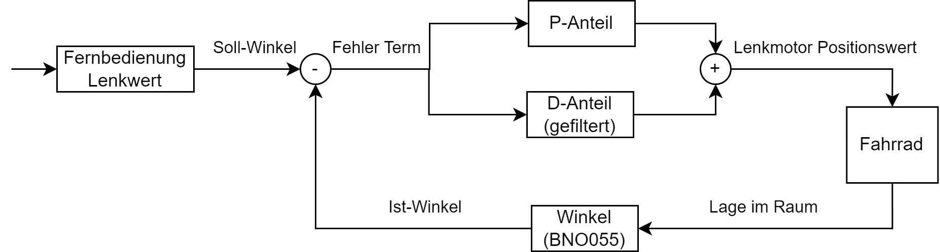
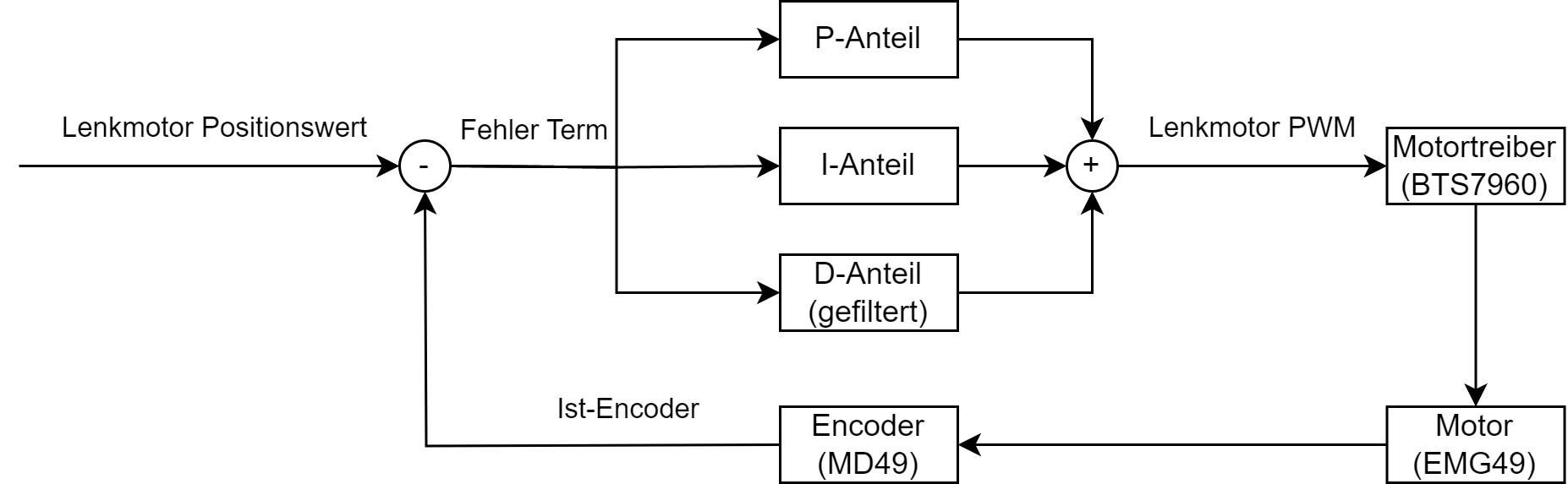
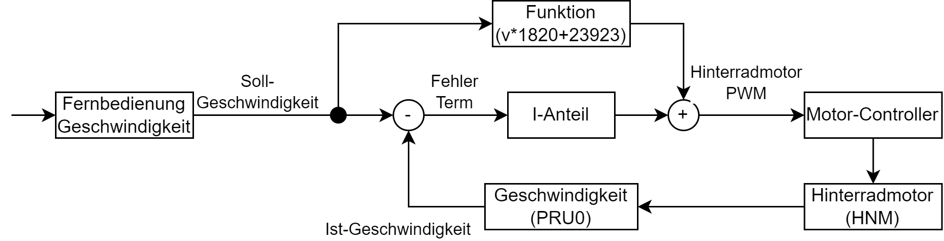
The outer lean loop maps the BNO055 angle to a target steering angle with a PD controller. The inner steering loop tracks that target with a PID controller and encoder feedback. Separately, the rear-wheel loop combines a calibrated feed-forward command with integral correction. Their measured rates in the final test were about 128 Hz, 184 Hz, and 6.6 Hz respectively.
The steering motor drives the handlebar through a belt.
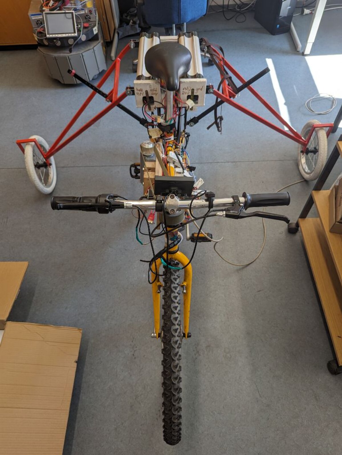
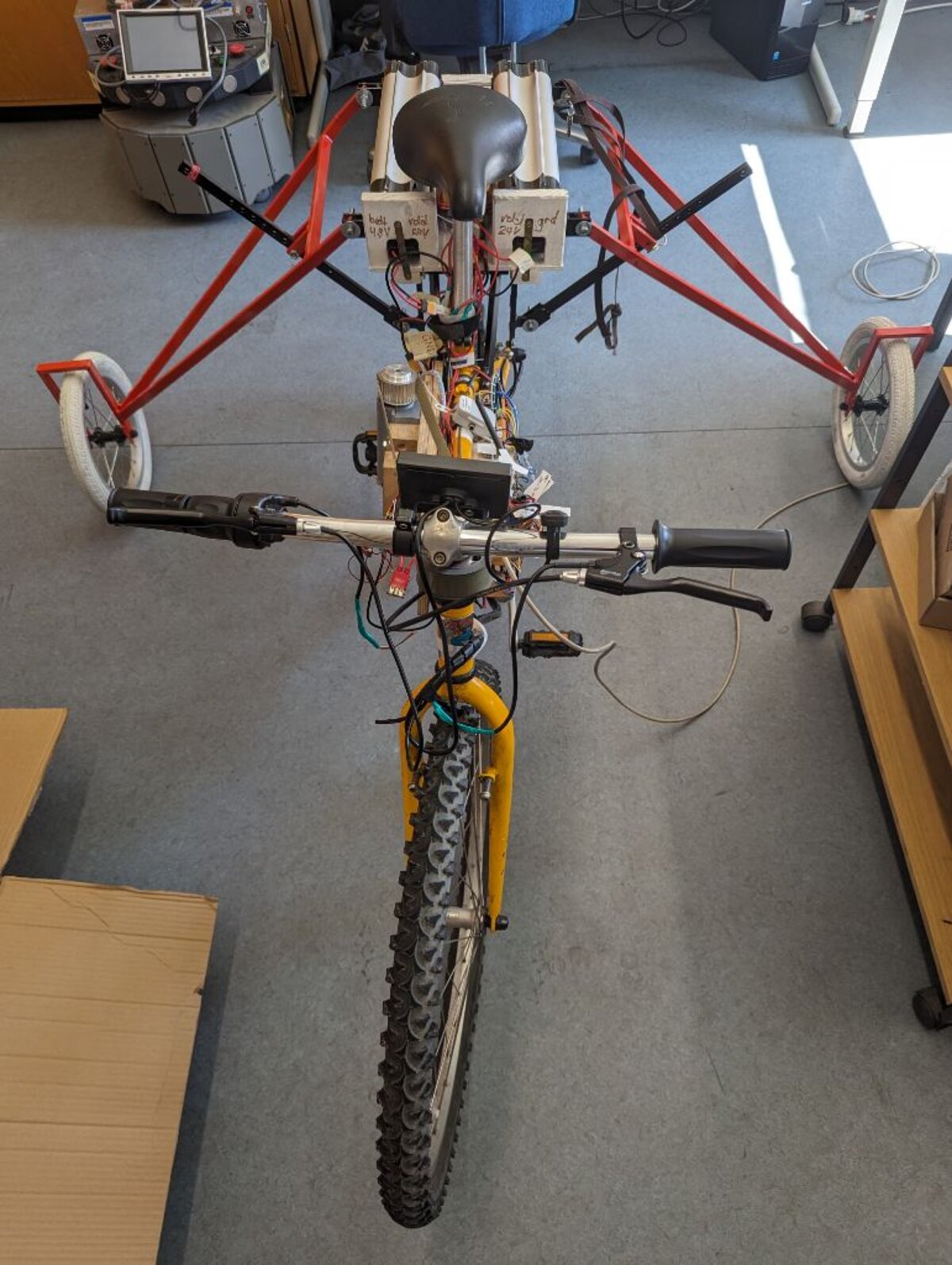
The EMG49 sits above the head tube and turns the handlebar through a belt drive. Its encoder feeds the steering loop through the MD49, while a BTS7960 supplies the motor current. Two adjustable support wheels limit a fall during tests. They are raised for a balancing run and lowered for setup work.
Characterise the plant before you tune the controller.
Before a PID controller can do useful work, you have to know how the motors actually respond. I measured the rear motor's PWM-to-speed response and the steering encoder's counts-per-degree relationship before tuning the loops.

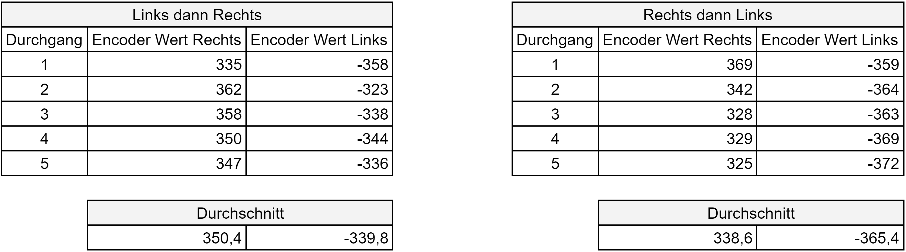
Bench tests first, then the complete bicycle.
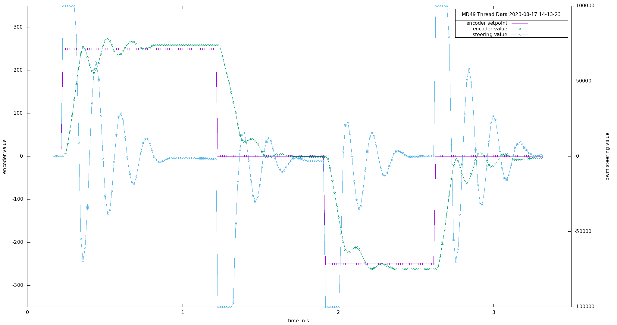
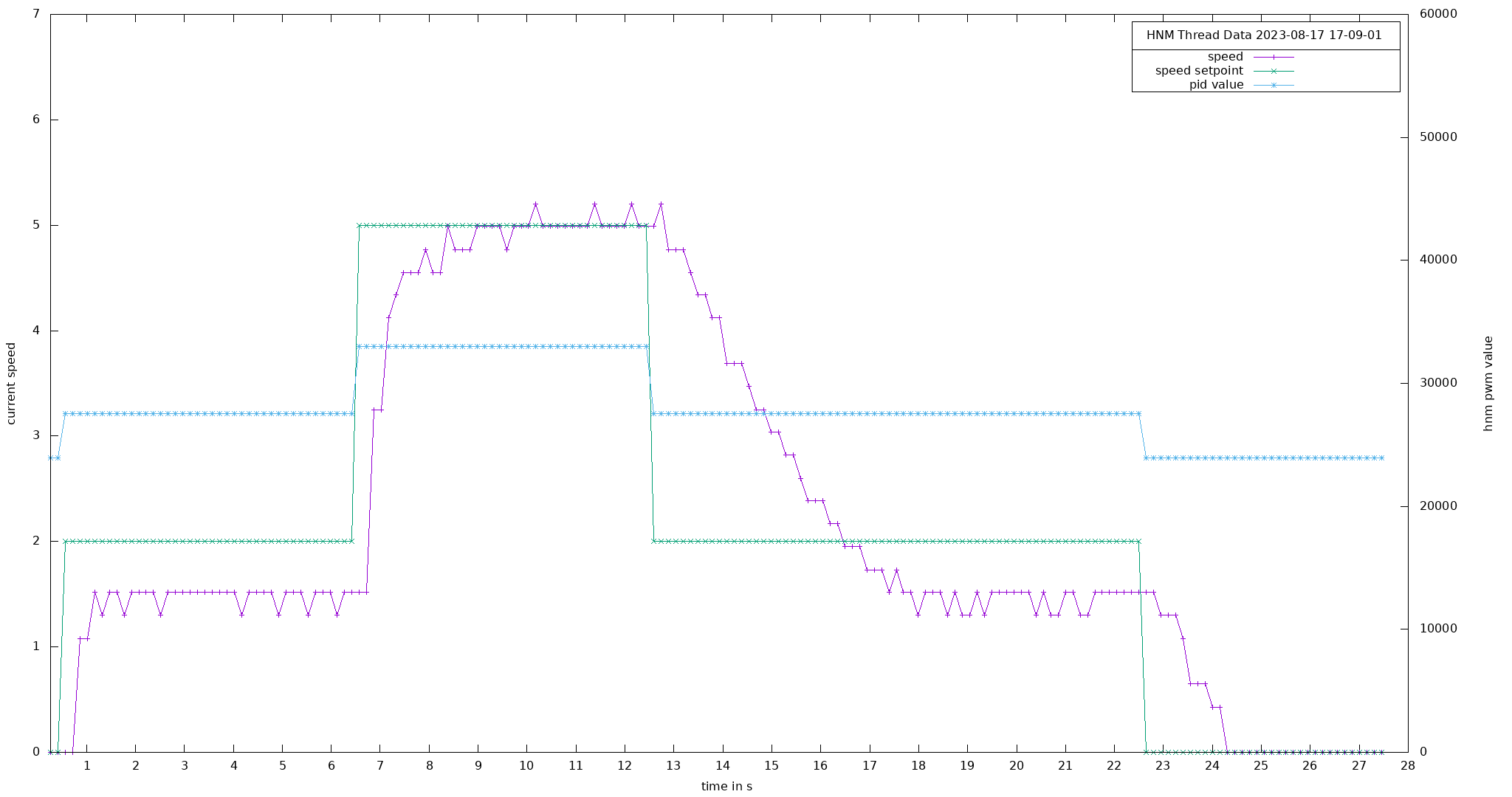
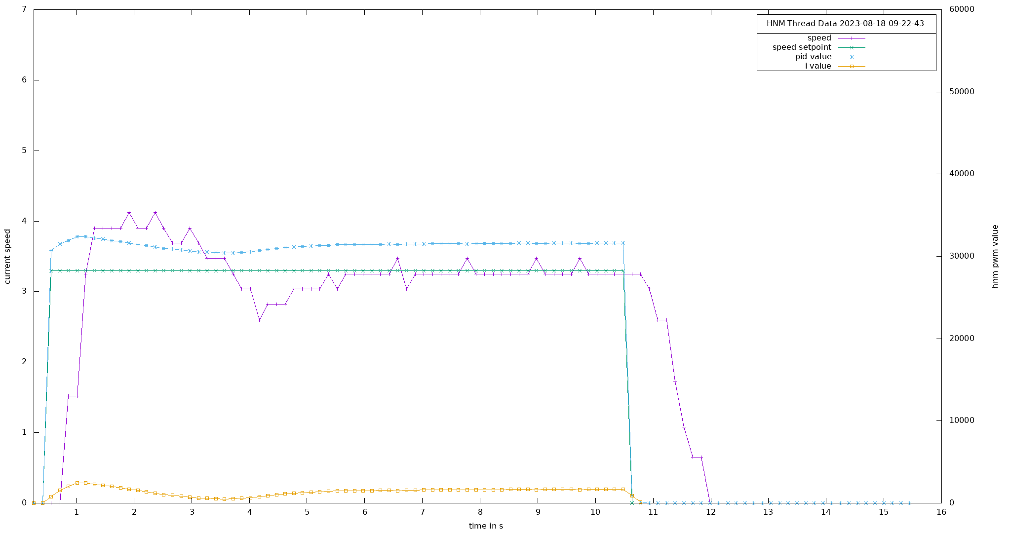
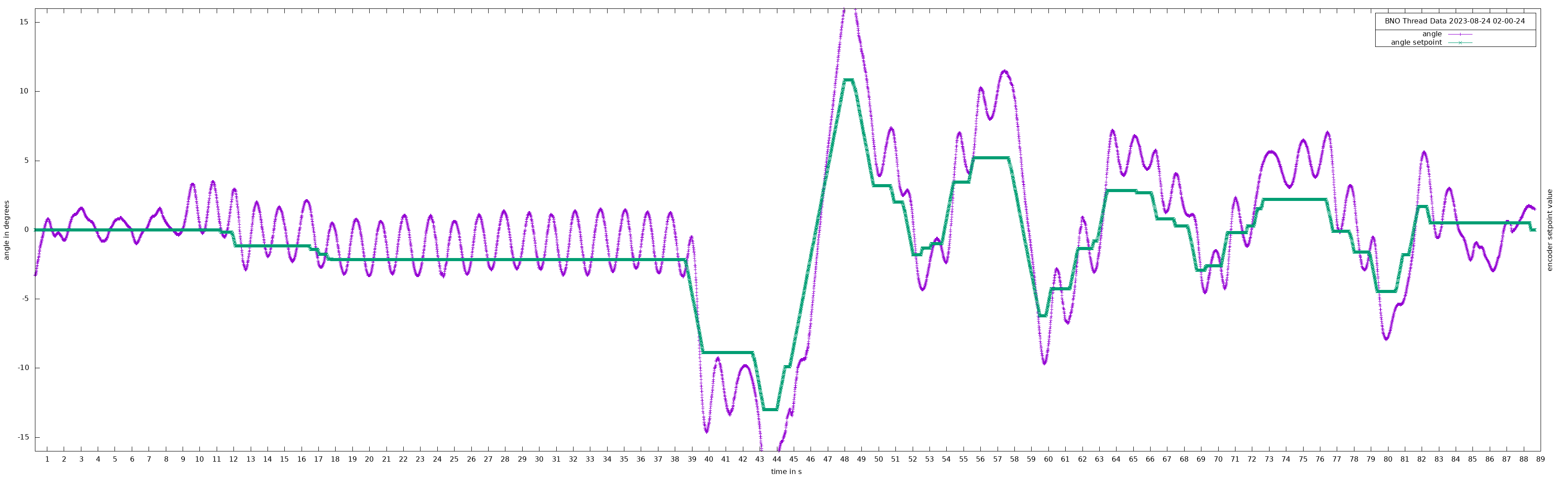
I tested the steering and rear-wheel loops separately before tuning balance on the complete bicycle. The archived CSV files and thesis plots cover tests from 17 to 24 August 2023. They show why a result needed a run identifier and conditions, not just a claim that the controller worked.
The result
What the final test established.
On 24 August 2023, the operator checked the bicycle, brought it to a 3.1 m/s target, and released it around second 8. It travelled mostly straight until about second 39, then completed a tight remotely commanded turn and several wider turns. Logs continue to roughly second 89. The thesis reports that the support wheels did not touch and concludes that the 60-second goal was met.
Under the hood
Tech stack
- C application on Debian Linux running on a BeagleBone Black
- PRU assembly (TI Code Generation Tools) for Hall-sensor sampling
- BNO055 over I²C for orientation; MD49 over UART for the steering encoder
- BTS7960 driver taking PWM + GPIO to run the EMG49 steering motor
- 2.4 GHz receiver handling rider inputs; Makefile build; per-thread CSV logging
Design decisions
- Active steering for balance instead of adding a reaction wheel
- Measure rear-wheel Hall transitions on the PRU, outside the Linux scheduler
- Use a PD lean controller, PID steering controller, and calibrated wheel-speed controller
- Write timestamped data from each worker so tuning decisions can be checked after a run
What I would do differently
- Make the controller depend on speed; the fixed PD gains became unstable at 5 m/s
- Add a real-time watchdog for blocked sensor or motor communication
- Replace relative steering zero with a reliable absolute reference
- Test tire pressure and load as controlled variables instead of setup details
The hardware platform came from earlier student work in the same lab. My thesis covers the software interfaces, controller design, calibration, and tests summarized on this page.